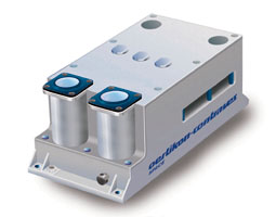
Paul Scherrer Institut

PSI HOME
SREM HOME
REM HOME
SREM Webmaster

Introduction
Design modularity
Key Performance Features
Host Spacecraft Accomodation
Calibration
SREM

NEWS HOME INSTRUMENT MISSIONS DATA PUBLICATIONS CONTACTS INDEX


Introduction

The Standard Radiation Environment Monitor is developed and manufactured by CONTRAVES SPACE AG in cooperation with the PAUL SCHERRER INSTITUT (PSI) under a development contract of the EUROPEAN SPACE AGENCY (ESA).

SREM performs a wide range of radiation monitoring functions in orbit, and downloads the results via the host spacecraft telemetry to a user on ground. It is designed as a standard equipment compatible with all common spacecraft interfaces and mission constraints.


SREM instrument
SREM


Top of page


Design modularity

The Standard Radiation Environment Monitor houses the following functional blocks:
  • Power supply with DC/DC converter with output voltages for the digital and the analog circuits, as well as for the detectors.
  • Three particle detectors with associated temperature sensors integrated in the detector housing.
  • Analog front end with low noise signal amplifiers and signal conditioning electronics.
  • Comparators with fifteen detection ranges.
  • Interface for remote total dose and temperature measurement sensors.
  • Signal processing electronics with host spacecraft interface for:
  1. Data processing and storage of scientific data
  2. Acquisition of housekeeping data and system health monitoring
  3. Telemetry and telecommand interface with host spacecraft.
SREM functional block diagram

Top of page


Key Performance Features

1. Mass 2.5 kg
2. Dimension 96 mm x 122 mm x 217 mm
3. Power  Consumption < 2W
Floating bus voltage 20 V to 50 V DC
4. TM/TC Compatibility with most spacecraft standards
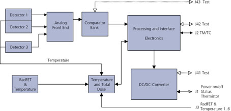
5. Sensors Three precision particle detectors (measurement error < 1%)
Internal total dose measurement
Internal temperature measurement
6. Operation Microprocessor, memory and data storage capacity for autonomous operation during several days
Data downloading on request via host spacecraft telemetry
Operational monitoring accessible from host spacecraft data handling system
7. Environment Compliant with all standard launcher vibration load spectra
Temperature range -20° up to +55 °C (operational)
-55° up to +80 °C (non-operat.)
Compliant with standard EMC/EMI requirements
Qualified for space vacuum
8. Lifetime & Reliability 0.85 for 10 years in-orbit operation and 3 years ground storage
Radiation tolerant components
ASIC's and FPGA are MIL-standard products which are space qualified with US and European programs
9. Versatility High degree of standardisation
Modular design and configuration flexibility allows to meet special user requirements
10. Options Thermal painting of MLI as specified by customer
Adaptation of host spacecraft TM/TC interface according to customers special request

Top of page


Host Spacecraft Accomodation

1. Mechanical Interface Mounting area 230 mm c 106 mm
Four holes Æ 4.3 mm
2. Thermal Interface Total contact area 2 x 14.5 mm x 122 mm
Black paint (optional MLI cover)
3. Electrical Power Interface Floating spacecraft bus 20 V to 50 V DC
Power consumption < 2 Watt
4. Power Control Interface On / Off command lines
Status interface switching
Housing temperature monitoring
5. Data Handling System Interface Telecommand interface differential or single ended
Telemetry interface differential or single ended
6. Remote Sensor Interface> Sensor bias source interface
Remote total dose sensor interface
Remote temperature sensor interface

Top of page


Calibration

The SREM is fully calibrated at the Proton Irradiation Facility (PIF) of the Paul Scherrer Institute (PSI), which also operates the dedicated SREM electron calibration source. The proton calibration is performed with protons up to 600 MeV, using an energy spectrum representative for the conditions in space. The calibration with electrons covers the range up to 5 MeV.

The numerical simulations of the detector response, performed with the GEANT code, are verified based upon the results of the calibration and provide therefore a reliable database for the system input signal response characteristics.

Strv1c/SREM proton response function Strv1c/SREM electron response function
Geometric factors of the 15 SREM detector channels aboard Strv1c for (left) protons and electrons. The geometric factors were determined with calibration measurements and Monte Carlo simulations.

Top of page